


Large outdoor areas require a different lighting strategy from conventional streets, pathways and small parking areas. Airports, ports, stadiums, highway interchanges and logistics yards may need wide coverage, long viewing distances and reliable illumination across extensive operating zones.
A properly designed High Mast Lighting System uses multiple floodlights installed at elevated positions to illuminate a large area from a limited number of mast locations. This can reduce pole density and provide flexible light distribution, but only when the luminaires, mast structure, foundation, controls and maintenance system are designed together.
The following guide explains the main technical factors that project owners, contractors, consultants and lighting designers should consider before selecting a high mast configuration.
1. Determine Whether High Mast Lighting Is Suitable
High mast lighting is normally considered when a large area must be illuminated from relatively few installation positions. It can be useful where numerous low-height poles would obstruct operations, increase cabling or create excessive infrastructure within the illuminated area.
Typical applications include:
Airport aprons and selected airport outdoor areas
Ports and container terminals
Stadiums and outdoor sports facilities
Highway interchanges and large junctions
Industrial yards and production areas
Logistics centers and freight terminals
Large parking areas
Railway and transportation facilities
Municipal squares and public plazas
Large commercial and recreational areas
A high mast installation is not automatically the best solution for every large site. The designer should compare it with medium-height poles, perimeter-mounted floodlights and building-mounted luminaires before making a final decision.
The comparison should consider lighting performance, pole positions, cable routes, structural requirements, maintenance access and total lifecycle cost.
2. Collect the Required Project Information
Accurate lighting and structural design begins with accurate project information. A supplier cannot determine the correct configuration from the total site area alone.
Before selecting products, collect the following information:
Site plan and illuminated-area dimensions
Location of roads, buildings, equipment and operating zones
Required average and minimum illumination
Required uniformity
Glare limitations
Proposed or available mast positions
Maximum acceptable mast height
Local wind conditions
Soil and foundation information
Input voltage and electrical distribution
Control and dimming requirements
Maintenance method
Required certifications and standards
Restrictions caused by aircraft, cranes, traffic or nearby buildings
The drawing should identify areas that need full illumination and areas where light should be restricted. This prevents unnecessary light from reaching nearby properties, control towers, road users or environmentally sensitive zones.
3. Select the Floodlights and Optical Distribution
The luminaire is responsible for directing light from the mast to the required area. An LED High Mast Light configuration should therefore be selected according to photometric performance rather than total wattage alone.
Important luminaire factors include:
Total luminous output
Luminaire efficacy
Beam angle
Asymmetric or symmetric light distribution
Optical efficiency
Glare control
Color temperature
Color rendering
Ingress protection
Impact resistance
Surge protection
Driver efficiency and control compatibility
Narrower beams can project light over longer distances, while wider beams cover areas closer to the mast. Many projects require several optical distributions on the same lighting frame.
For example, floodlights directed toward distant boundaries may use a narrower distribution, while luminaires covering the area around the mast may require a wider distribution. The final combination should be confirmed through lighting simulation using the actual photometric files.
4. Determine the Mast Height
Mast height affects coverage, glare, luminaire quantity, structural loading and maintenance. A taller mast can illuminate a wider area, but it also increases the distance between the luminaires and the ground.
The preliminary height may be discussed according to the application:
Application | Preliminary Height Range | Main Design Consideration |
Large parking areas and public plazas | Approximately 15–25 m | Balanced coverage, visual comfort and surrounding buildings |
Industrial and logistics yards | Approximately 20–35 m | Operating routes, equipment movement and working visibility |
Highway interchanges | Approximately 20–35 m | Long-distance visibility, traffic guidance and glare control |
Ports and container terminals | Approximately 25–45 m | Large operating areas, cranes, containers and wind exposure |
Stadiums and sports facilities | Approximately 20–40 m | Playing-area illumination, vertical lighting and glare |
Airport aprons | Project-specific | Aircraft operations, restricted zones, glare and aviation requirements |
These values are preliminary planning references rather than fixed specifications. The final height should be determined through lighting simulation, structural calculations and the applicable project standards.
Using a taller mast does not necessarily reduce the total energy requirement. The luminaires may need more output to deliver the required illumination over the increased distance.
5. Position the Masts According to the Site Layout
Mast positions should be selected before finalizing the quantity and direction of the floodlights. Poor positioning can create shadows, uneven illumination or interference with site operations.
Possible arrangements include:
Centralized lighting from one or more positions inside the area
Perimeter lighting directed inward
Corner-mounted lighting
Linear arrangements along transport or logistics zones
Combined perimeter and internal lighting
The selected locations should avoid vehicle routes, crane paths, aircraft operating areas, emergency access routes and locations where future construction may occur.
For ports and industrial facilities, containers, machinery and stored materials can create significant shadows. The lighting design should evaluate the site under realistic operating conditions rather than assuming an entirely empty ground surface.
6. Calculate Luminaire Quantity and Power
Total installed wattage alone does not indicate whether the project will meet its lighting requirements. Luminaire quantity and power should be calculated together with mast height, optical distribution, aiming direction and maintenance factor.
The design should evaluate:
Required average illuminance
Minimum illuminance
Horizontal and vertical illumination
Uniformity
Task visibility
Area dimensions
Mast positions
Surface reflectance
Environmental dirt and dust
Expected light depreciation
Increasing the number of floodlights may improve coverage, but it also increases electrical load, wind-exposed area and the weight supported by the lighting frame.
The final quantity should therefore be coordinated by the lighting designer, structural engineer and manufacturer.
7. Evaluate Illuminance, Uniformity and Glare
High mast lighting should provide sufficient visibility without producing excessive glare or strong differences between bright and dark zones.
Important evaluation criteria include:
Average horizontal illuminance
Minimum horizontal illuminance
Overall uniformity
Vertical illuminance where required
Glare toward drivers, operators and nearby buildings
Light spill beyond the project boundary
Brightness of the luminaires when viewed from normal operating positions
Glare can be reduced through suitable optics, accurate floodlight aiming, appropriate mast positions and controlled luminaire output.
Floodlights should not be aimed only by visual estimation during installation. Their orientation should follow the approved lighting design, with aiming angles recorded for commissioning and future maintenance.
8. Choose Between Fixed and Liftable Structures
High mast lighting frames can be fixed at the top of the pole or designed to move vertically for maintenance.
Configuration | Main Characteristics | Suitable Conditions |
Fixed lighting frame | The floodlights remain permanently installed at the top of the mast | Projects with suitable elevated maintenance equipment and controlled access |
Lowerable lighting frame | The luminaire frame can be lowered toward ground level through a lifting mechanism | Projects requiring easier ground-level inspection and luminaire maintenance |
Dual-lift structure | Separate lifting arrangements can support different equipment or lighting groups | Complex projects requiring independent maintenance or operational flexibility |
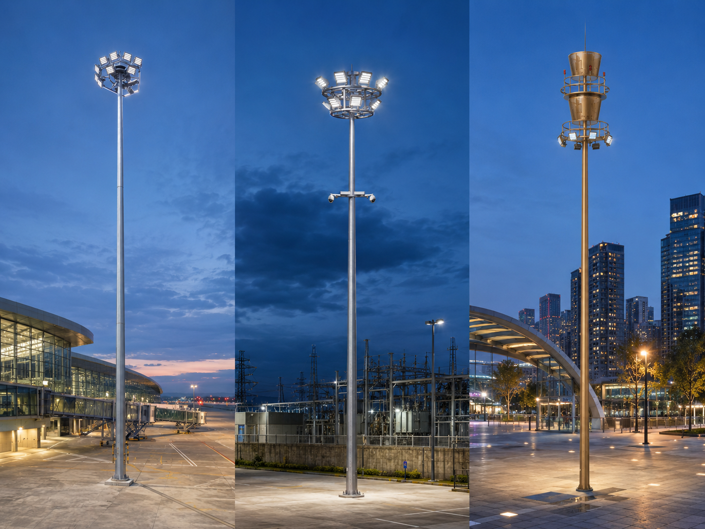
Smart integrated mast | Lighting may be combined with communication or monitoring equipment | Smart-city, transportation and infrastructure projects requiring multiple functions |
A Liftable High Mast Light can reduce the need to perform routine luminaire maintenance at the full pole height. However, the winch, cables, locking mechanism, electrical connections and safety devices require professional design, installation and inspection.
The correct choice depends on maintenance access, mast height, site safety rules, equipment availability and lifecycle cost.
9. Understand the Lifting and Locking Mechanism
A lowerable lighting frame normally includes a winch or drive system, lifting cables, guide components, locking devices and electrical connections. These parts must operate as one coordinated system.
Important considerations include:
Rated lifting capacity
Number and arrangement of lifting cables
Mechanical locking at the operating position
Emergency stopping
Overload protection
Cable guidance inside the pole
Electrical connection during lifting
Ground-level operating controls
Prevention of uncontrolled movement
Inspection and lubrication access
The lighting frame should be securely locked when it reaches its normal operating position. The lifting cables should not be treated as the only permanent support for the frame unless the selected engineering design specifically provides for that arrangement.
Operating instructions, load limits and inspection requirements should be supplied with the completed system.
10. Check Structural and Wind-Load Requirements
A high mast supports multiple luminaires and a large lighting frame at an elevated position. Wind loading is therefore a critical part of the structural design.
The calculation should consider:
Basic local wind speed
Terrain and exposure category
Total mast height
Pole geometry and sectional structure
Luminaire quantity and projected area
Lamp-frame dimensions
Communication or monitoring equipment
Maintenance platform where applicable
Dynamic and fatigue effects
Connection between pole sections
Base plate and anchor bolts
The pole wall thickness and section dimensions should be determined through engineering calculations rather than selected from the mast height alone.
If cameras, antennas, 5G equipment, signage or other devices will be added, their weight and wind-exposed area must be included before the structural design is finalized.
11. Design the Foundation and Anchor-Bolt Assembly
The foundation transfers the mast load into the ground. Its dimensions depend on the mast structure, wind load, soil conditions, anchor-bolt arrangement and applicable engineering requirements.
The foundation design should confirm:
Soil-bearing capacity
Foundation depth and dimensions
Concrete strength requirements
Reinforcement arrangement
Anchor-bolt diameter and spacing
Base-plate dimensions
Cable-entry position
Drainage
Finished ground level
Earthing connection
The anchor-bolt template should be checked before concrete is poured. Incorrect bolt spacing, orientation or projection can prevent the mast base from being installed correctly.
Project-specific foundation drawings should be reviewed by a qualified local engineer because soil conditions and construction standards vary between locations.
12. Adapt the Design to the Application
Different large-area applications have different visual and operational requirements.
Application | Main Lighting Priority | Special Considerations |
Airport apron | Aircraft servicing and ground-operation visibility | Glare, aircraft movement, control-tower visibility and airport requirements |
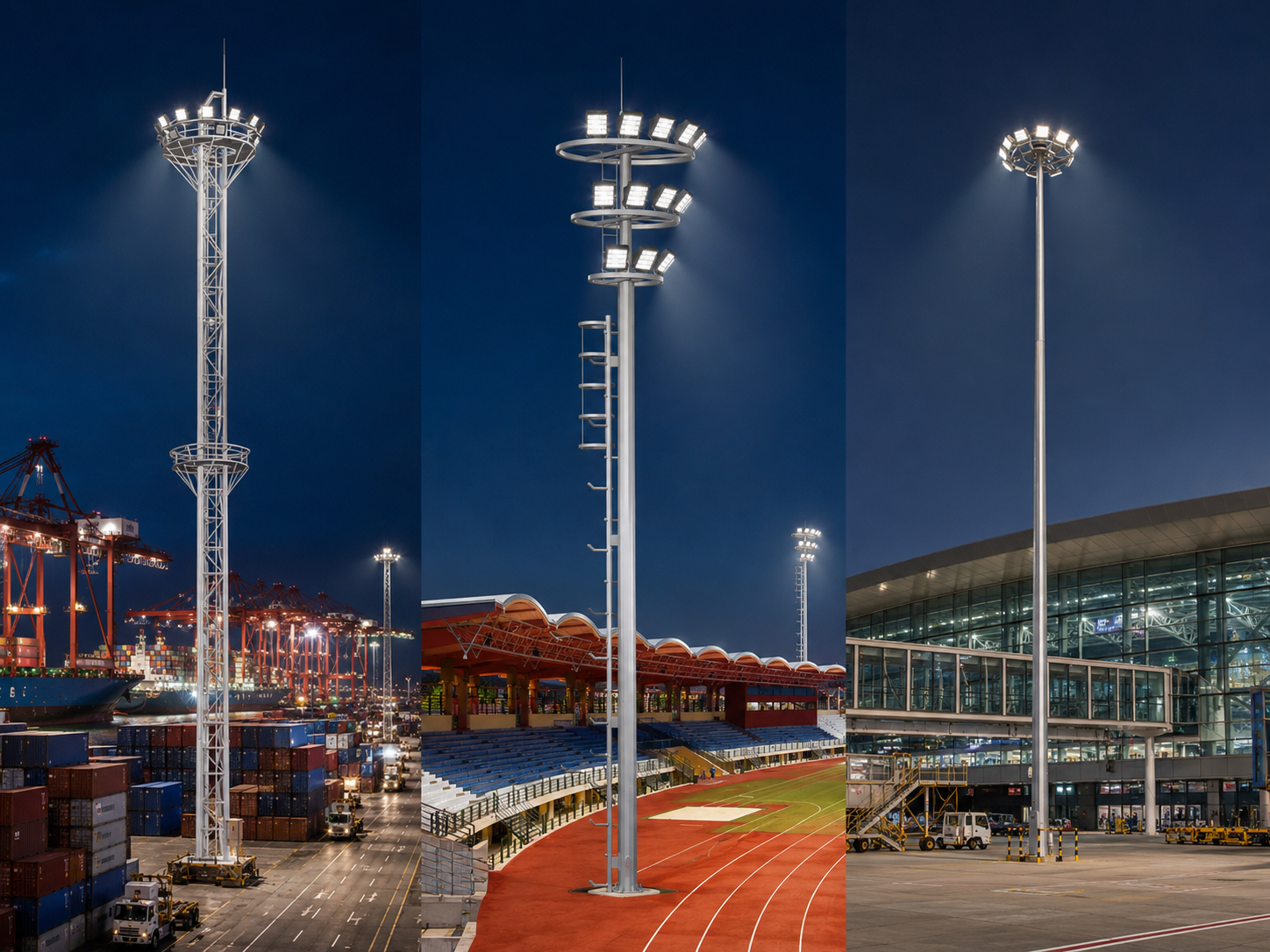
Port and container terminal | Cargo handling, vehicle movement and large working-area coverage | Cranes, container shadows, corrosion, wind and maintenance access |
Stadium and sports field | Playing-area visibility and vertical illumination | Player and spectator glare, cameras, aiming direction and event requirements |
Highway interchange | Traffic guidance and visibility through complex road geometry | Driver glare, road classification, barriers and nearby properties |
Industrial and logistics yard | Safe operation of vehicles, equipment and workers | Moving machinery, stored materials, dust and changing operating zones |
Public square | General visibility, pedestrian comfort and architectural coordination | Surrounding buildings, decorative appearance and nighttime activity |
Dedicated products may be more suitable than one universal mast design. For example, an airport apron installation may prioritize controlled aiming and maintenance safety, while a port project may require stronger corrosion protection and greater consideration of large moving equipment.
13. Plan the Electrical and Control System
The electrical design should coordinate the total lighting load, power distribution, switching, dimming and protection requirements.
Possible system components include:
Main distribution cabinet
Individual mast control cabinet
Circuit breakers and electrical protection
Surge-protection devices
Contactor or relay control
Photocell switching
Time-based control
0–10V or DALI dimming
PLC-based centralized control
Remote operating-status monitoring
Energy-consumption monitoring
Fault alarms
Large sites may divide the luminaires into several switching groups. This allows part of the installation to operate during low-activity periods while full illumination is available during peak operation.
The control strategy should match the actual site-management capability. An advanced platform provides limited value if operators cannot maintain the communication network, controllers and software.
14. Check Outdoor Protection and Corrosion Resistance
High mast equipment may be exposed to rain, dust, temperature changes, salt, industrial pollution and continuous wind.
The project should evaluate:
Luminaire ingress protection
Impact resistance
LED driver enclosure protection
Surge and lightning protection
Steel mast surface treatment
Fastener and cable corrosion resistance
Control-cabinet sealing
Drainage inside the mast
Operating temperature range
Coastal or industrial exposure
Hot-dip galvanizing is commonly used to protect steel mast sections. Additional coating or surface-treatment requirements may be considered for coastal, chemical or visually sensitive environments.
The final protection level should be confirmed for the selected luminaires, control equipment and structural configuration.
15. Complete a Professional Lighting Simulation
Lighting simulation should be completed before the mast positions, luminaire quantity and beam distributions are finalized.
A DIALux or equivalent project model can evaluate:
Average illuminance
Minimum illuminance
Uniformity
Vertical illumination
Glare
Light spill
Mast quantity and location
Floodlight quantity
Beam combinations
Aiming angles
Installed power
Estimated energy consumption
The simulation should use the actual site dimensions and photometric files of the proposed floodlights. Generic luminaires or approximate optical data may produce results that do not represent the final installation.
Large machinery, buildings, stadium structures and other significant obstructions should be included where they affect the lighting result.
16. Plan Installation and Commissioning
Installation requires coordination between civil, structural, electrical and lighting teams.
Before erecting the mast, verify:
Foundation strength and curing
Anchor-bolt position
Base-plate compatibility
Mast-section sequence
Electrical cable preparation
Lifting equipment capacity
Weather and wind conditions
Site exclusion zone
Luminaire and frame assembly
Earthing connection
Commissioning should include electrical testing, control verification, lifting-system testing where applicable and nighttime inspection of the completed lighting result.
Floodlight aiming should be compared with the approved design. If adjustments are required, the final angles and control settings should be recorded for future maintenance.
17. Plan Long-Term Maintenance
Maintenance planning should begin during design rather than after the equipment has been installed.
Inspection Item | Main Checks |
LED floodlights | Operation, light output, lens condition, sealing and aiming direction |
Lighting frame | Fasteners, deformation, corrosion and luminaire mounting |
Lifting mechanism | Winch, cables, guides, locking devices and safety controls |
Steel mast | Surface condition, section connections, access door and corrosion |
Base and foundation | Anchor nuts, settlement, cracks, drainage and corrosion |
Electrical system | Cables, connections, protection devices, control cabinet and earthing |
Control platform | Switching, dimming, communication, fault alarms and operating schedule |
Inspection frequency should be determined according to the environment, equipment design, operating hours and project safety requirements.
Ports, coastal projects and dusty industrial locations may require more frequent inspection and cleaning than ordinary municipal areas.
18. Avoid Common High Mast Lighting Mistakes
18.1 Selecting the System by Total Wattage
Total wattage does not confirm coverage, uniformity, glare or optical performance.
18.2 Choosing the Mast Height Before Simulation
Mast height should be coordinated with the site dimensions, floodlight optics and required illumination.
18.3 Ignoring Large Obstructions
Buildings, cranes, containers and stored materials may create shadows that are not visible in an empty-site calculation.
18.4 Using One Beam Angle for Every Floodlight
Large areas normally require different distributions for near, middle and distant zones.
18.5 Adding Equipment After Structural Design
Cameras, antennas and communication equipment add weight and wind load and should be included before the mast is manufactured.
18.6 Ignoring Maintenance Access
A fixed lighting frame may create unnecessary maintenance difficulty if suitable elevated equipment is not available.
18.7 Using a Generic Foundation
Foundation requirements change with mast height, wind load, soil conditions and anchor-bolt design.
18.8 Failing to Record Floodlight Aiming
Without documented aiming angles, replacement or maintenance work may change the approved lighting distribution.
19. Information to Send to the Manufacturer
To receive an accurate high mast recommendation, the project enquiry should include:
Project country and city
Site drawing and illuminated-area dimensions
Application type
Required illumination and uniformity
Proposed mast quantity and positions
Preferred or maximum mast height
Local wind-speed requirement
Soil or foundation information
Input voltage and frequency
Required operating schedule
Control and dimming requirements
Fixed or lowerable lighting-frame preference
Additional cameras, antennas or communication equipment
Corrosion and environmental conditions
Required standards and certifications
Estimated project quantity
Complete information allows the manufacturer to coordinate the mast structure, floodlight quantity, beam distribution, lighting frame, lifting mechanism, foundation interface and controls as one project-specific system.
Conclusion
High mast lighting design involves much more than placing several powerful floodlights on a tall pole. The mast positions, pole height, optics, aiming angles, structural loading, foundation, electrical controls and maintenance method must work together.
A project-specific simulation and structural design can help achieve the required illumination while controlling glare, reducing unnecessary energy consumption and providing safe long-term operation.
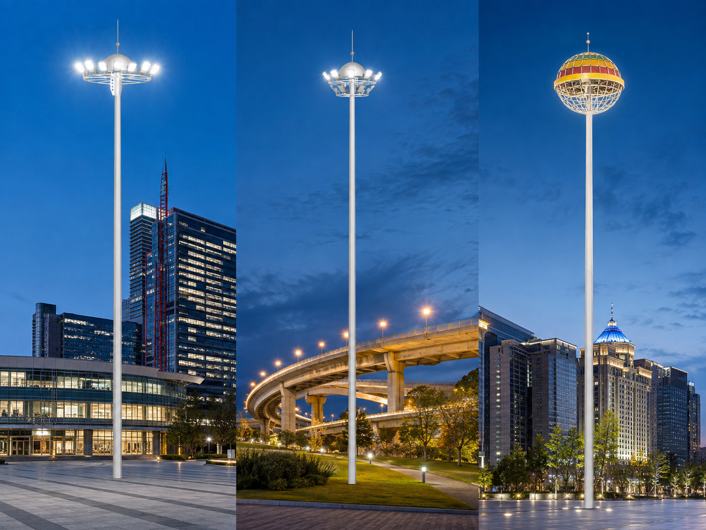
Baode Lighting provides circular, decorative, airport, port, stadium, mid-mast, dual-lift and smart integrated lighting configurations. Customers can provide project drawings, lighting requirements and environmental information to receive a customized product configuration and engineering recommendation.
FAQ
1. What is high mast lighting?
High mast lighting uses multiple floodlights installed on a tall mast to illuminate a large outdoor area from one centralized position.
2. How tall should a high mast pole be?
The height depends on the application, site dimensions, required illumination, floodlight optics, mast positions and local restrictions. The final height should be confirmed through simulation and structural design.
3. How many floodlights are required?
The quantity depends on luminaire output, beam distribution, mast height, illuminated area, required uniformity and glare limitations. There is no universal quantity suitable for every project.
4. Is a lowerable lighting frame necessary?
It is not required for every installation, but it can simplify inspection and maintenance where suitable elevated access equipment is unavailable or difficult to use.
5. How are high mast lights protected against strong winds?
The pole, lighting frame, luminaires, connections, base plate, anchor bolts and foundation should be designed according to the local wind conditions and complete installed equipment load.
6. Can cameras and 5G equipment be installed on the mast?
Yes, when the mast is specifically designed for the additional equipment. The weight, position, power supply, cabling and wind-exposed area must be included in the engineering calculations.
7. Why is lighting simulation important?
Simulation helps confirm mast locations, luminaire quantity, beam angles, illumination, uniformity, glare and installed power before the equipment is manufactured and installed.
8. Can Baode provide a customized high mast configuration?
Yes. Mast height, luminaire quantity, lighting frame, optical distribution, lifting system, surface treatment, controls and foundation interface can be configured according to the project requirements.


Komentář
(0)